
There are at least three cases where cutting objects into smaller components could be your best option:
- Your model is too big and does not fit inside the print volume.
- Your model does not have any suitable flat surface to serve as a base to be placed on the bed.
- You want to avoid using support material or at least decrease the amount of support material.
The first case is obvious. If it’s too big, there is no way of printing the model as one piece. Cases number 2 and 3 are a little bit trickier to recognize. Imagine you’re printing a perfect sphere. No matter which orientation you choose, only a tiny area will be in contact with the bed, and the print will inevitably fail. However, when you cut the sphere in half, you can easily place each hemisphere on the print bed and print it without problems. Such a simple cut can be made directly in Slic3r as explained in our Beginner’s guide for Slic3r Prusa Edition.
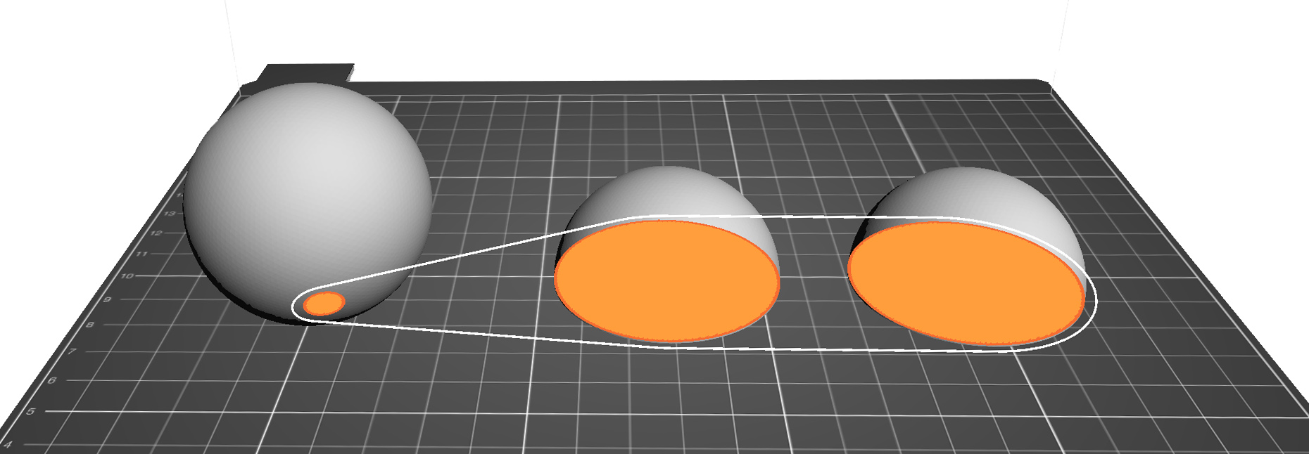
Printing sphere in one piece vs simple cut along the Z axis
However, a simple cut along the Z-axis is not always enough. Sometimes, you’ll want to cut along the X or Y axis, or even with an arbitrary positioned plane. For that, the simple cutting in Slic3r is not enough. A good option is to use Meshmixer, cutting model in it is fast and easy.
Simple plane cut in Meshmixer
- Select Edit – Plane Cut
- A plane will appear. You can move it around using the three-axis gizmo
- You can also define a plane by holding down the left mouse button and moving the mouse
- Select whether you want to keep both halves (slice) or just one (cut) from the Cut-type drop-down menu
- Select the hole filling method from the Fill-type drop-down menu. The default usually works great. You can learn more about the various filling methods in Meshmixer documentation.
- Accept the cut. The model will still look like one piece.
- Select Edit – Separate Shells to split the model into two
- Select one of the newly created halves, and click Export from the menu on the left to generate an STL file. Repeat the process for the other half.
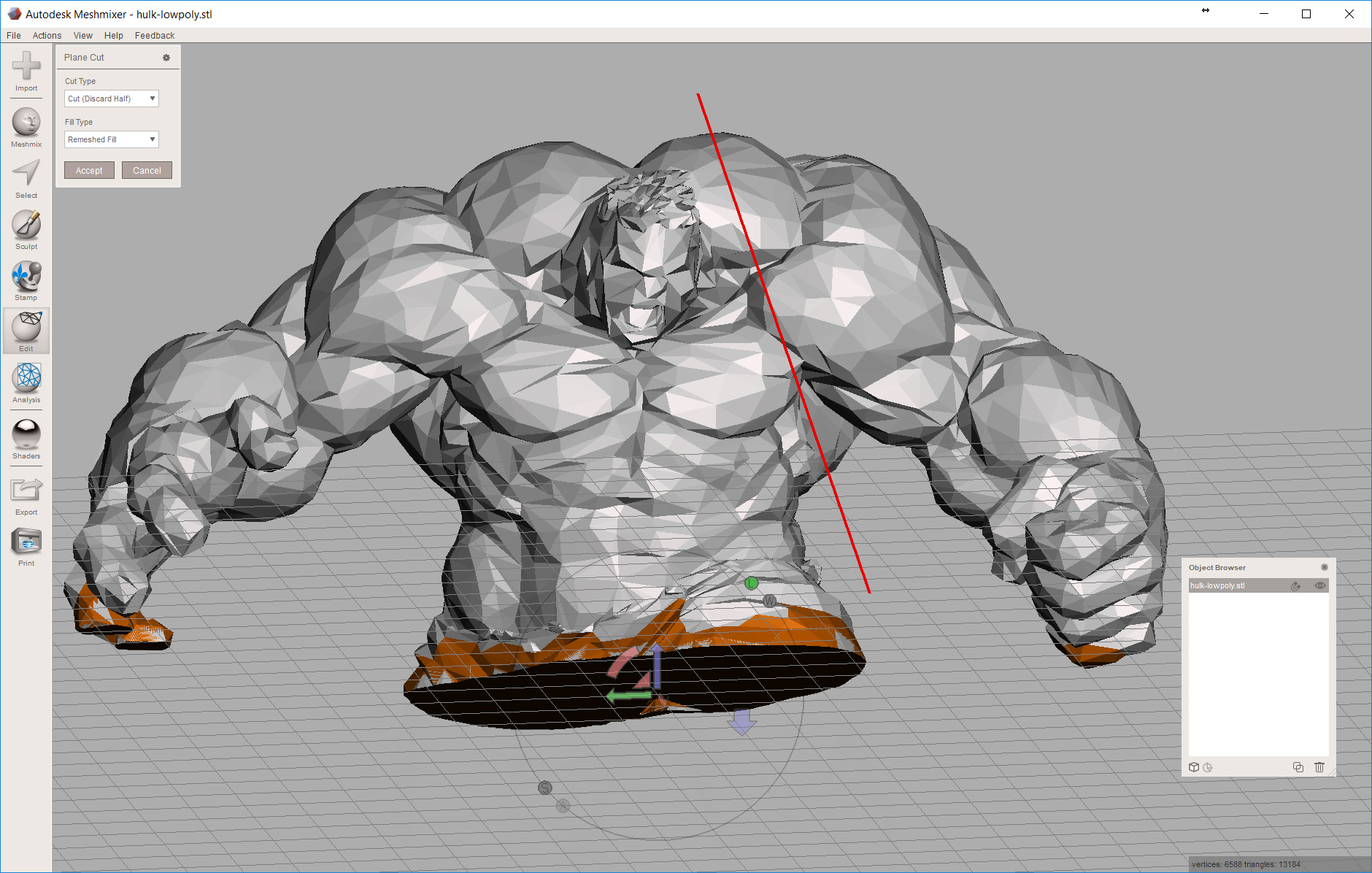
A plane cut of the Hulk
Advanced cut in Meshmixer
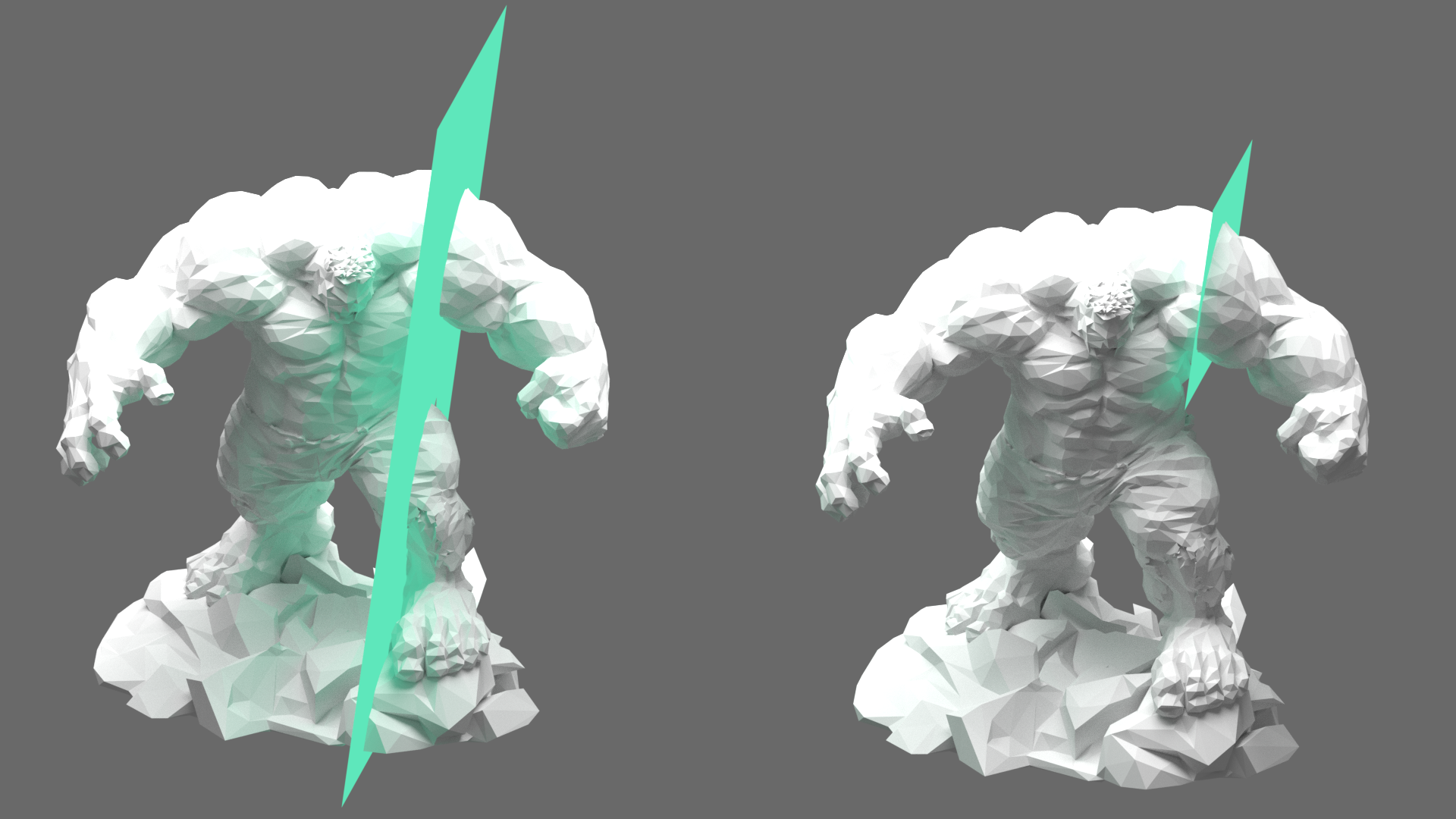
Cut with an infinite plane vs a cut with dimension constrained plane
To prevent this behavior, we can specify a smaller area to be affected by the cut. Everything outside of this selection will ignore the plane cut and stay as one piece.
- Choose Select from the left menu. By default, a brush tool is selected.
- By holding down the left mouse button, you can paint over parts of the model to select them. Selected triangles turn orange.
- Alternatively, choose the lasso tool using the switch in the top left corner.
- By holding down the left mouse button, draw a curve/loop. Everything inside the loop will be selected. Unlike the brush tool, this will also select triangles on the other side of the model, that are not facing the camera.
- Once your selection is complete, a new menu will appear on the left side. Select Edit – Plane cut from the new menu. If you accidentally use the Edit – Plane cut from the main toolbar, your selection will be discarded.
- Proceed the same as with a simple cut. Only selected triangles (orange) will be affected by the cut.
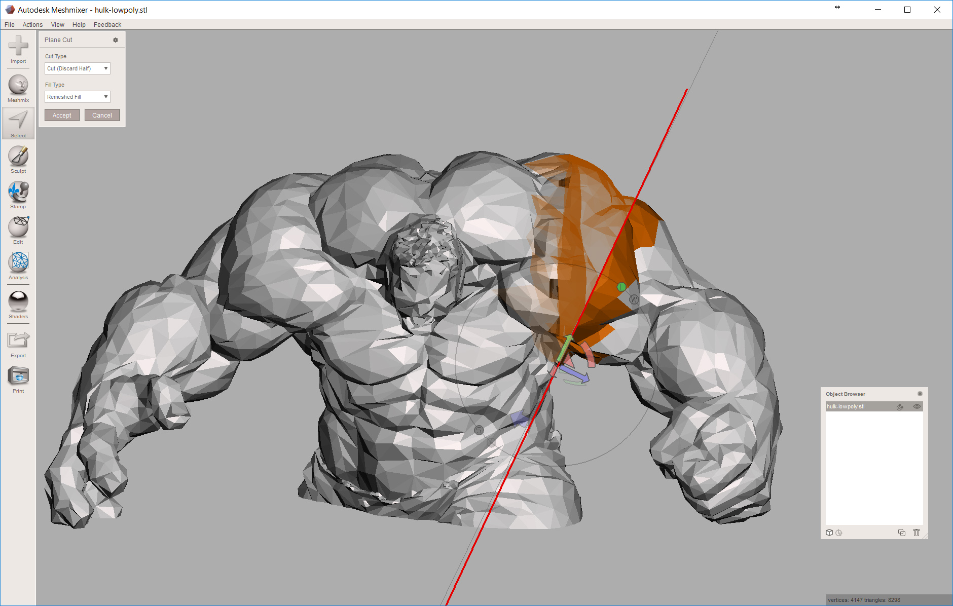
A cut through selection (right arm). Note that the cut does not affect Hulk’s body, even though the plane intersects it
Adding aligning pins
When you finished printing individual parts, you’ll have to glue them together. This can get somewhat tricky and you’ll have to hold the pieces perfectly aligned as the glue cures. If the glue takes too long to cure, it’s difficult to keep the parts aligned the whole time and sometimes it’s impossible to use a clamp. And if it takes just a second (e.g., super-glue with an activator), you only have one shot and if you misalign the parts, it’s already too late to fix it. For this reason, it’s a very good idea to add some aligning pins. Doing this in Meshmixer is at the edge of its capabilities, but it’s doable. In a future tutorial, we’ll tackle the same problem with a more powerful, but also more complex software.
- Cut the model (follow the steps for simple or advanced plane cutting)
- Open the objects browser View – Show Objects Browser (CTRL+Shift+O)
- Hide one of the objects by clicking on the eye icon in the Objects Browser
- Select Meshmix, pick a primitive (a cylinder for example) and drag it to the plane of the model, created by the cut
- Position and scale the primitive, so that it can work as an aligning pin
- You can move the primitive around by dragging the sphere gizmo in the middle of the primitive
- You can scale the primitive by dragging the arrow shape next to the sphere gizmo
- In the Drop Solid menu on the left change Composition mode to Create New Object
- Hit Accept when you’re happy with the scale and position of the primitive
- Select the primitive and duplicate it by hitting Shift+C or by clicking on the duplicate icon in the Objects browser
- Repeat this two times so that you end up with 3 copies of the primitive
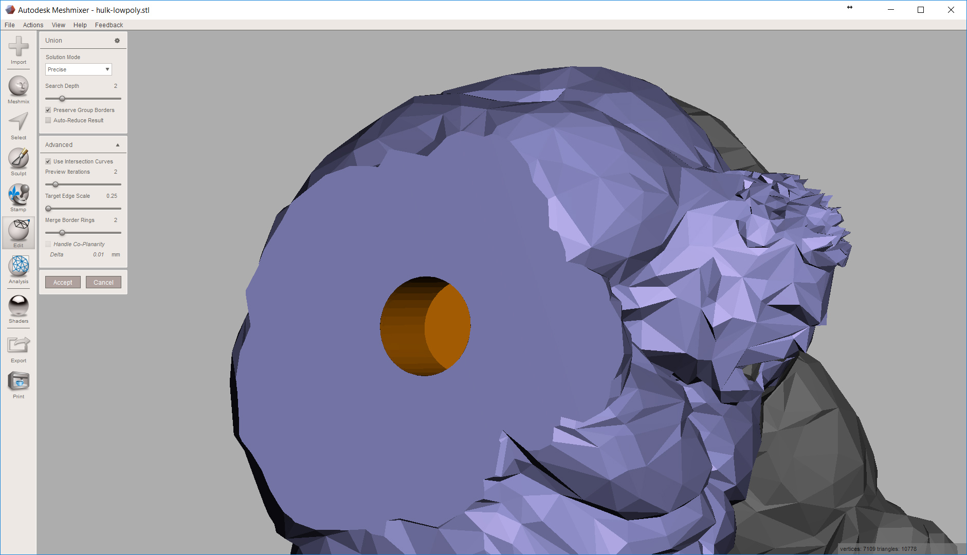
- Select the model (Hulk) and then the primitive (cylinder), then click Edit – Boolean Difference
- In the new window on the left, untick Auto-Reduce Result, tick Use Intersection Curves and decrease Target Edge Scale
- You can get detailed information about these settings in the Meshmixer documentation
- After you hit Accept, the primitive will disappear. Luckily, we made a copy of it in step 8
- Repeat the Boolean Difference with the other half of the model (steps 9-10)
- This consumed another copy of the primitive.
- Export both halves of the cut object and the last copy of the primitive one by one as STL
- When you’re preparing the G-code in a slicer, it’s a good idea to scale the primitive down a tiny bit to create clearance for the aligning pin
You can download Low Poly Hulk model by Tom Davis from MyMiniFactory.
great tutorial. I am struggling with one part I am hoping someone can help me with. Once I have sliced and created two parts I need to add the pin. When I drag in the cylinder primitive and drop it on the sliced surface, it is not perpendicular by default. In fact it is at at noticeable angle. In the video it appears that the pin is defaulted to be normal to the cut plane. For me, I am not able to rotate and position very easily. Any help on dropping in the primitive and making relatively aligned whith the surface would be helpful.
When you drag the cylinder from the Meshmix menu, it should either be perpendicular to whatever surface you drag it on or it should be in the default position where it’s oriented the same as the default axis.
You can try this if you open Meshmixer and from the 6 options choose “Import Bunny”. Then Meshmix menu and drag the cylinder. If you drag the cylinder by the sphere gizmo, it should do a live preview of the cylinder changing orientation to always stay perpendicular to the current surface under the cursor.
If that doesn’t work, then maybe try updating Meshmixer or alternatively you can use the Edit – Transform to manually position, rotate and scale the cylinder. It’s not as elegant, but it works.
HI, I’m a reconstructive surgeon starting to deal with MeshMixer software for my virtual surgery planning and I need some help.
I would like to ask you if the task I want to accomplish is realistic with this software…can you help me?
Immagine you need to actually cut your Hulk model being extremely precise.
So that you need to creat and print a cutting guide.
What I would like to do is to create this cutting guide based on the surface of the object in order that the guide will fit perfectly on the model…Is that possible?
Well, I wouldn’t say it’s impossible, but it’s not the perfect tool either.
Meshmixer always creates the plane (cut) perpendicular to the view plane, which is extremely intuitive. But it’s not the best for exact positioning, as you’ll have to orient your view perfectly and that means you might not be able to see exactly what you’re doing.
I would go with a modeling software, that lets you position the plane first and then lets you cut the model with a boolean operation. Blender (or Maya, 3DS Max…) is pretty good in this regard, but unlike Meshmixer, things are starting to get pretty complex in these programs.
Over-simplified tutorial in Blender would be: Open the model you want to cut in Blender. Press Shift-A and choose to add a Plane, position it exactly where you need it. Select the model to be cut, duplicate it, then in the right panel add the Boolean modifier (for one copy choose Difference, for the other Intersection) and Apply the modifier.
I know I’m super late to the game but did you ever find a solution to doing this? I’m also trying to make cutting guides but struggling.
“In a future tutorial, we’ll tackle the same problem with a more powerful, but also more complex software.”
Did that tutorial ever get written? I didn’t see anything.
Thank you for the guide! I used this to slice a flip flop because I have size 14 feet. Not sure how alignment pins and superglue will last on footwear, but ey, this TPU gotta get printed as something right?!