


“Allow me to introduce myself — I am a CL4P-TP steward bot, but my friends call me Claptrap! Or they would, if any of them were still alive. Or had existed in the first place!”
This is how Claptrap, a character from the game series Borderlands, introduces himself when you first meet him. I think he’s hilarious ?. 3D printing our favorite characters from movies or games is a lot of fun. But if they could talk and light up, that would be next level. And so that’s exactly what we’re going to do today!
List of features:
- A programmable LED eye
- Eye blinks when Claptrap talks
- Can be set to any color, can be animated
- An audio player and a speaker
- SD card slot for audio storage
The 3D model
First, we need the model to print. As always, you can download the finished model from PrusaPrinters, but let’s quickly talk about how we created it because it could help you with your own project.
Rather than starting from scratch, we’ve downloaded a really nice Claptrap model created by Chaos Core Tech (they even have a video about it) and used Blender to modify it. The function that we’ve used over and over is the boolean modifier, which lets you subtract one mesh from another.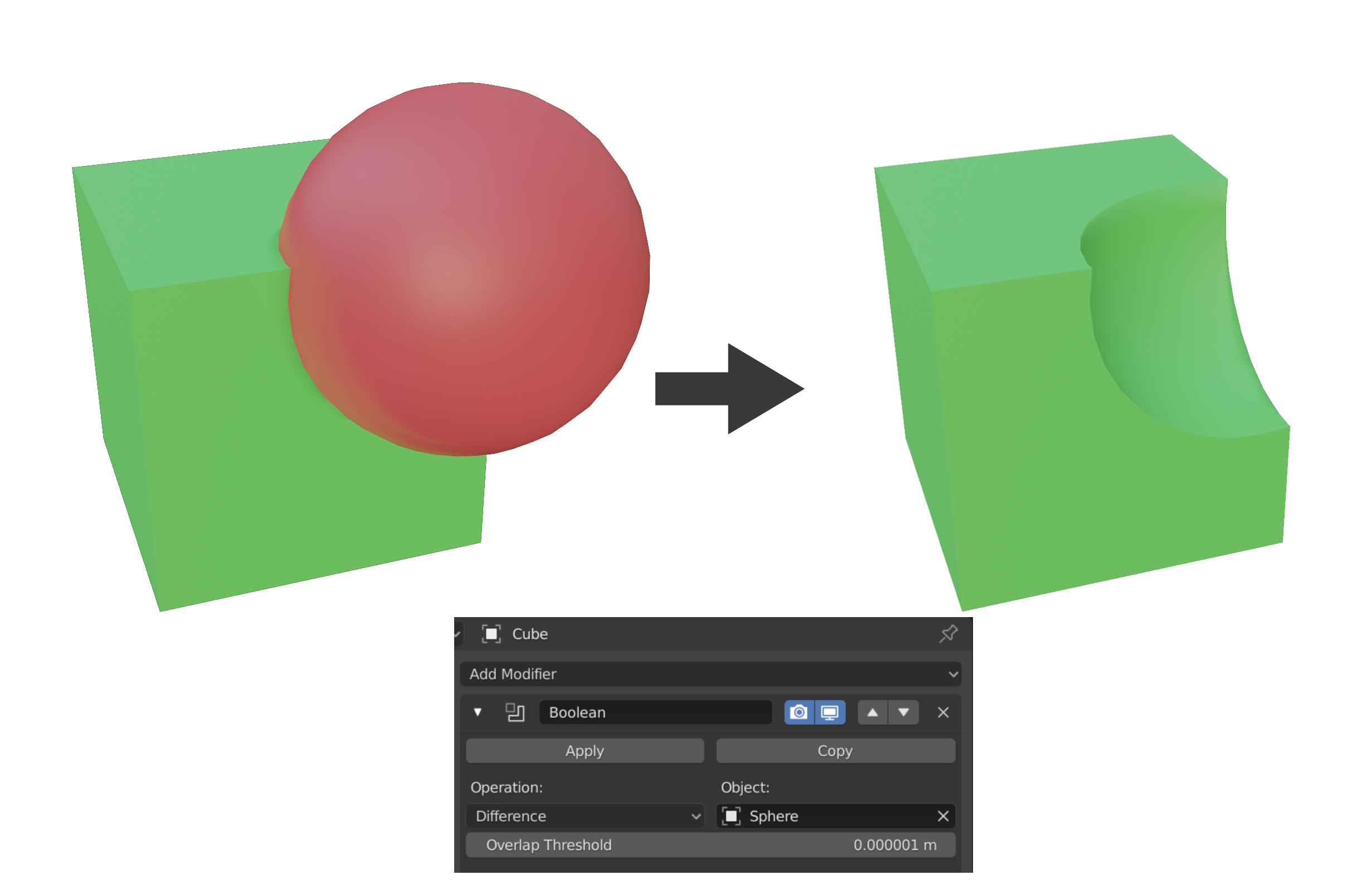
We need space for the electronics and a way to access it. So we’ve cut the top of the body and then cut out a big rectangular hole, essentially hollowing the main body. Then we’ve separated the eye and created a hole for the speaker. By modifying the original front vent cover we’ve made a new one, that can be printed separately. We’ll use it to hide the speaker hole. To make it easier to print, we’ve also separated the shoulder covers. Lastly, using the sculpting tool, which we have a separate article about, we’ve added dents and scratches to the body to make it look worn out. Modifying an existing model is a really quick and effective way to create what you need. If you want to share your remix, don’t forget to check that the license of the original model lets you do that.
Printing
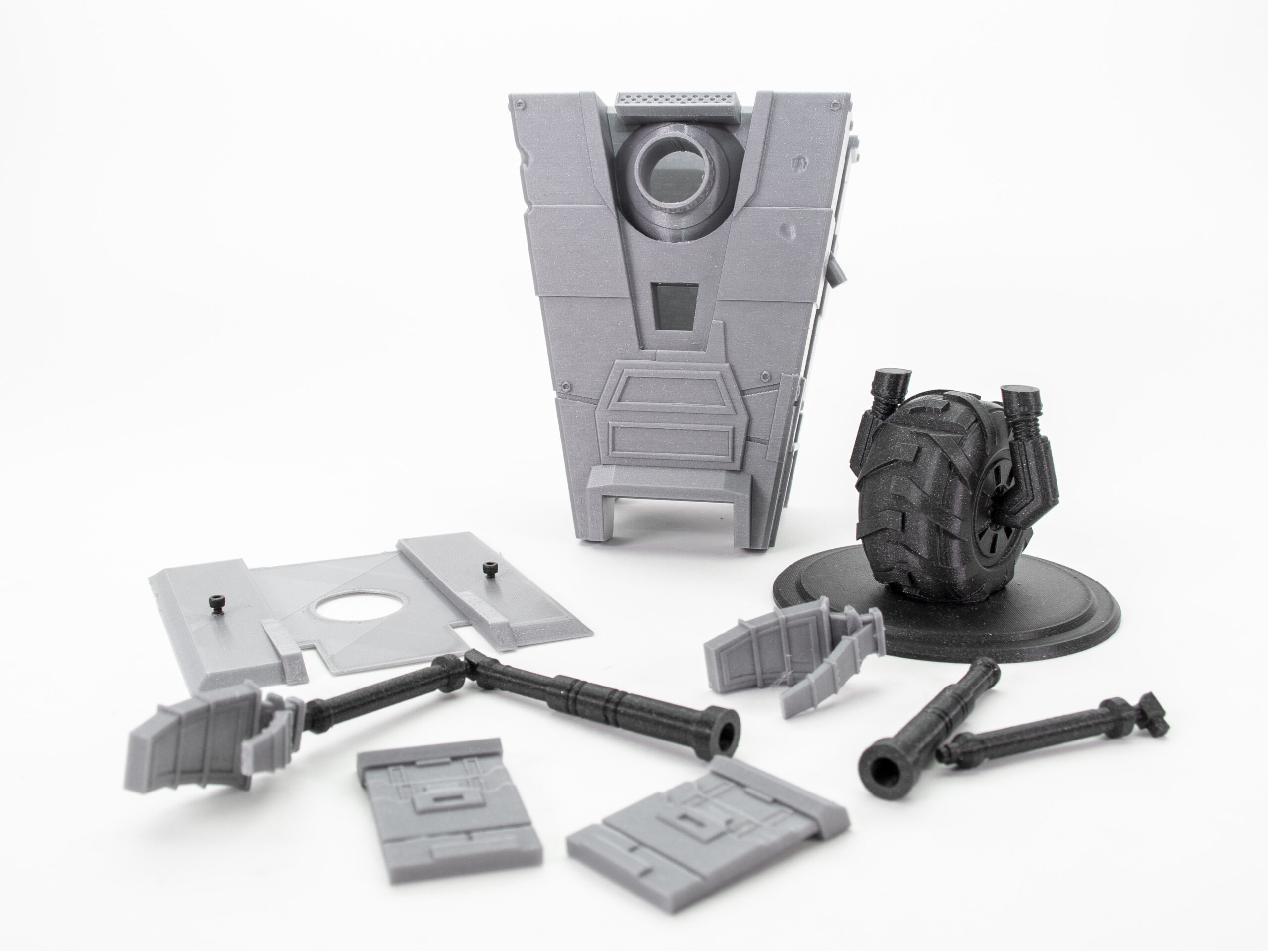
The majority of the model will be painted, so the color of the filament doesn’t matter too much. However, there are some exceptions – for example, to print the wheel, we picked our Prusament Galaxy Black and we’ll leave it partially unpainted. We printed most parts from PLA. It’s easy to print with, has great detail and especially for the big body piece, it’s really nice that the material doesn’t warp. The arms are quite thin, so we picked PETG instead to increase their durability. The LED holder was also printed from PETG.
Printing the lens, though, that can be quite tricky! Following the steps in our 3D printed lenses and other cool transparent objects article, we printed the lens from ABS, sanded it and polished it. We don’t really use ABS anymore these days (there are better alternatives/successors, like ASA), but for transparent objects, it works quite well. If you have access to an SLA printer, using it for the lens would be even better.
We scaled the whole model up, but it can still be printed even on the Original Prusa MINI. Feel free to change the scale of the model, just keep in mind that the smaller the model, the more challenging it will be to fit in the electronics. Let’s leave Claptrap disassembled for now, it will make painting him a lot easier later on.
Arduino and part list
The brain of all the electronics will be a good-old Arduino. Specifically, an Arduino Nano clone with a micro-USB port. If you’ve never programmed Arduino before, we went over the absolute Arduino basics in our 3D print a media control volume knob article, so check it out. It’s pretty easy, so don’t let it discourage you!
List of parts:
- Arduino Nano (or any other compact Arduino microcontroller) (Amazon, Aliexpress)
- WS2812B led strip (Amazon, Aliexpress)
- you can also buy WS2813, which can still work with one LED chip dead, due to an extra data line
- DFPlayer Mini + Micro SD card (Amazon, Aliexpress)
- 8Ω 0.5W speaker (Amazon, Aliexpress)
- An arcade button (Amazon, Aliexpress)
- Or any other button, but you’ll have to adjust the top over STL
- Arduino jumper cables + Micro USB cable
- (Optional) 18650 charger and case (Aliexpress)
Creating the programmable LED eye
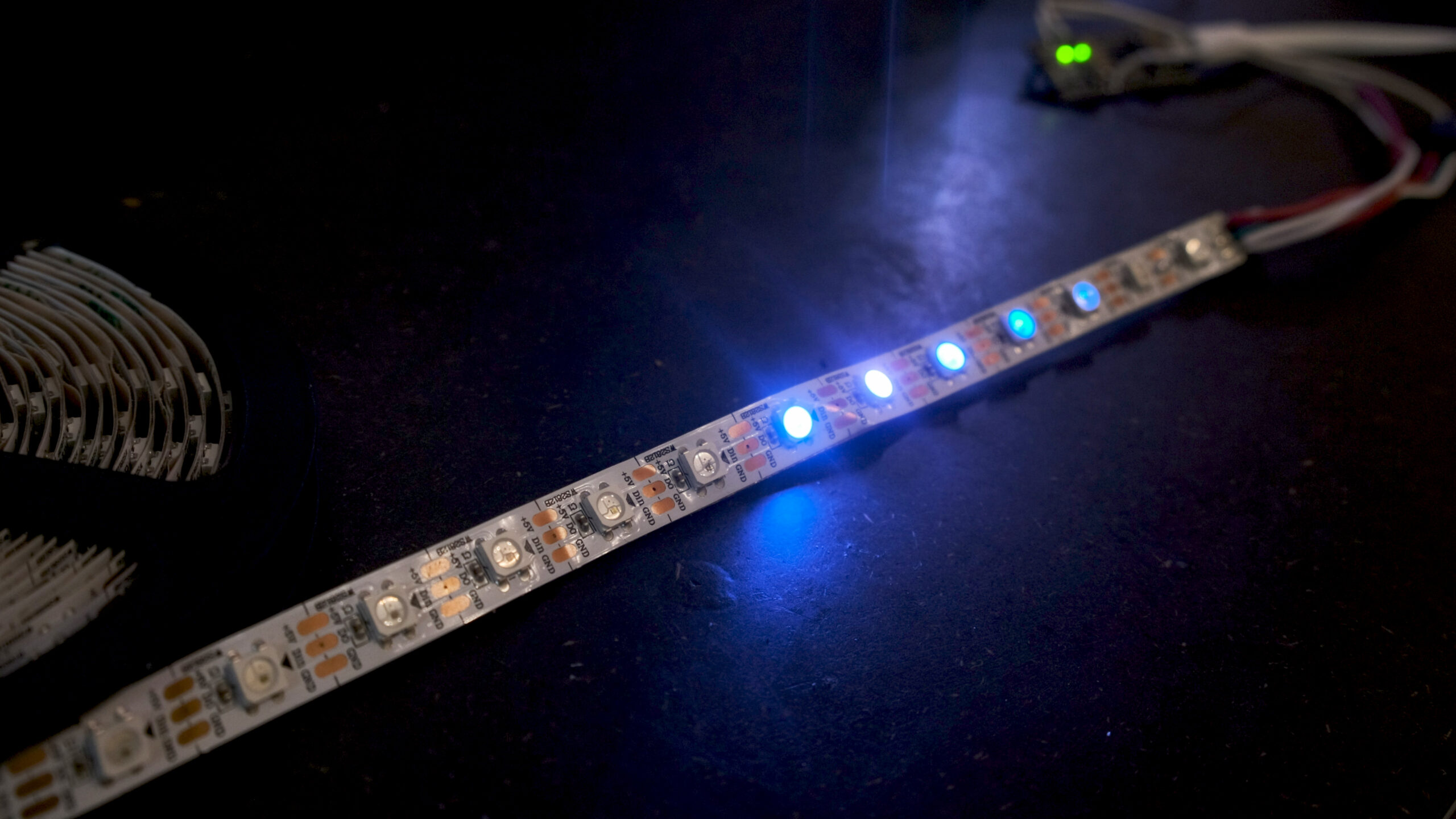
An LED strip, which allows you to change the color and intensity of each individual LED chip is arguably one of the most fun electronics parts. Unlike traditional LED strips, which are often powered by 12V or 24V, programmable LED strips usually run on 5V. That’s really handy because you can use the same power source for both the Arduino and the LED strip, such as a small cell phone powerbank.
In our previous article about Lighting up 3D prints, we used an RGB LED strip. It can change color, too, but only of the entire LED strip at once. Such LED strips have 4 wire connections – one for the ground and then one for each the red, green and blue channel. To adjust the color, we’d have to regulate the voltage of each color channel individually. That sounds like too much work, right?
On the other hand, a programmable LED strip has only 3 wire connections – the ground (minus), VCC (5V) and the data pin. The data pin is where the magic happens. We’re going to use an Arduino library that will handle the data sending for us. But if you’re curious how it works anyway, here’s a simple description. A programmable LED strip uses a timing-based shift register. You start sending data to the first LED chip. It keeps the first 24bits (8bits for each red, green and blue) and forwards the rest to its output pin. For every new pulse and a packet of 24bits, the data gets shifted to another chip. Once the last chip is reached, all of the LEDs display a color based on the currently loaded data.
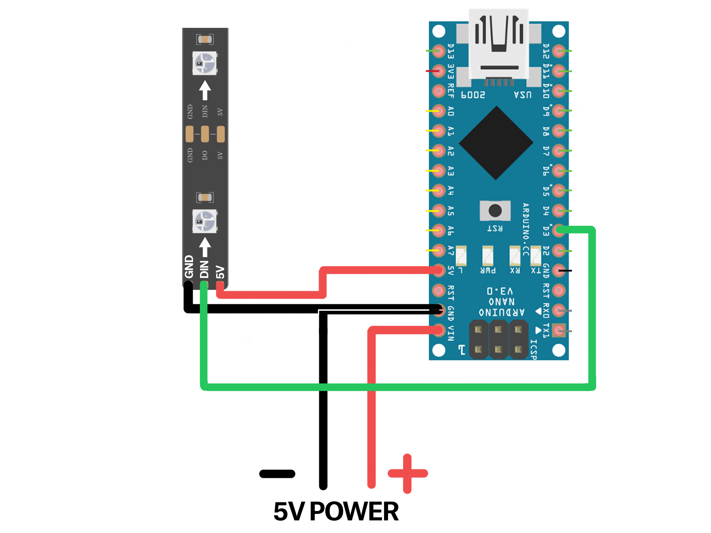
Normally, you should power the LED strip from the power source directly. However, the LED strip for the eye is so short, that we can simply take 5V from one of the Arduino 5V pins. Other than the ground, we also need to connect the data pin, use any free data pin on the Arduino, we picked pin 3.
You can often get away with no soldering by using the Arduino jumper wires. But since you’ll have to solder the cables to the LED strip, we might as well solder everything else too. Before you solder both sides, pull the wires through the LED holder! Otherwise, you’ll have to unsolder them again, speaking from experience here ?.
Soldering
Soldering is something everyone can learn with a bit of practice. Many beginners smear the solder around and try to force it where they need it. The trick is that once heated properly, the liquid tin will flow where you need it on its own without you moving the soldering iron around.
To solder a wire to an LED strip:
- Pre-tin the LED pads
- Touch the pad on the strip with the soldering iron for 2-3 seconds
- Add solder to create a nice round bubble of tin
- Do not overheat the connection, move away with the soldering iron as soon as the round bubble forms
- Pre-tin the wire
- Clamp or weigh the wire down so that it doesn’t move around much when you touch it with the tip of the soldering iron
- Touch the end of the wire with the soldering iron for 2-3 seconds
- Add solder and let it flow on its own through the wire
- Move away with the soldering iron as soon as the wire has enough tin
- Re-heat the pre-tinned pad by touching it with the soldering iron
- Immediately after that push the pre-tinned wire on the pad
- Use tweezers or pliers
- Move away with the soldering iron, but hold the wire in
- In the end, you should still have a nice and round surface covering the pad and the cable
Soldering pins or wires to the Arduino follows a very similar workflow:
Arduino audio player – speaker wiring
Hooking up the electronics for an audio player is just slightly more complex than the LED strip. In order to avoid dealing with sd card readers and amplifiers, we picked an all-in-one solution. DFPlayer is a small and low price MP3 module with a simplified output directly to the speaker. It has an SD card slot, which we’ll use for audio file storage. And it has RX/TX pins, which make communication with the Arduino just a matter of soldering two wires.
For the speaker – the DFPlayer datasheet suggests picking a speaker with power less than 3W. We bought a pack of cheap 8Ω 0.5W speakers. Alternatively, you can salvage a pretty good speaker from an old laptop or tablet.
Solder the connections according to the diagram. Please note the 1K resistor on the DFPlayer RX line. Our Arduino uses 5V on data lines, whereas the DFPlayer uses 3.3V, so the resistor is necessary to compensate for the difference. There are Arduino boards that also run on 3.3V (one version of Arduino Pro Micro), but they’re not very common.

Uploading the audio files
Make sure that the micro SD card is formatted as FAT32. Create a folder in the root directory called “mp3”. Place the audio files into this folder. The DFPlayer specification says the files should be named 0001.mp3, 0002.mp3, etc. For us, any file name worked, but your mileage may vary. Then insert the SD card into DFPlayer.
Programming the Arduino
- Download and open the Arduino sketch in Arduino IDE
- We’re going to use the FastLED and DFRobotDFPlayerMini library
- Select Sketch – Include library – Manage libraries
- Search for “FastLED” (author: Daniel Garcia)
- Select version 3.3.2 (we had problems with version 3.3.3)
- Click install
- Install the DFRobotDFPlayerMini library in the same way
- Select Sketch – Include library – Manage libraries, search for the library name and hit Install
- You can use the latest version available
- Select the correct board with Tools – Board – (Arduino Nano in our case)
- Connect the Arduino to your PC and select Tools – Port – COM? (you should see another COM except for COM1, e.g. COM3, select that one)
- Hit Upload
The code has lots of comments that should explain everything that’s going on in it. Feel free to play with it. For example, you can pick whether the voice lines should be played sequentially or in random order by (un)commenting one of these lines.
//myDFPlayer.next();
myDFPlayer.randomAll();
Painting
If you want to keep it really simple, all you’ll need is a couple of brushes and a set of acrylic colors. However, we took the opportunity to ask David, our in-house artist, who prepares models for fairs and shows, to describe his workflow on a model like this.
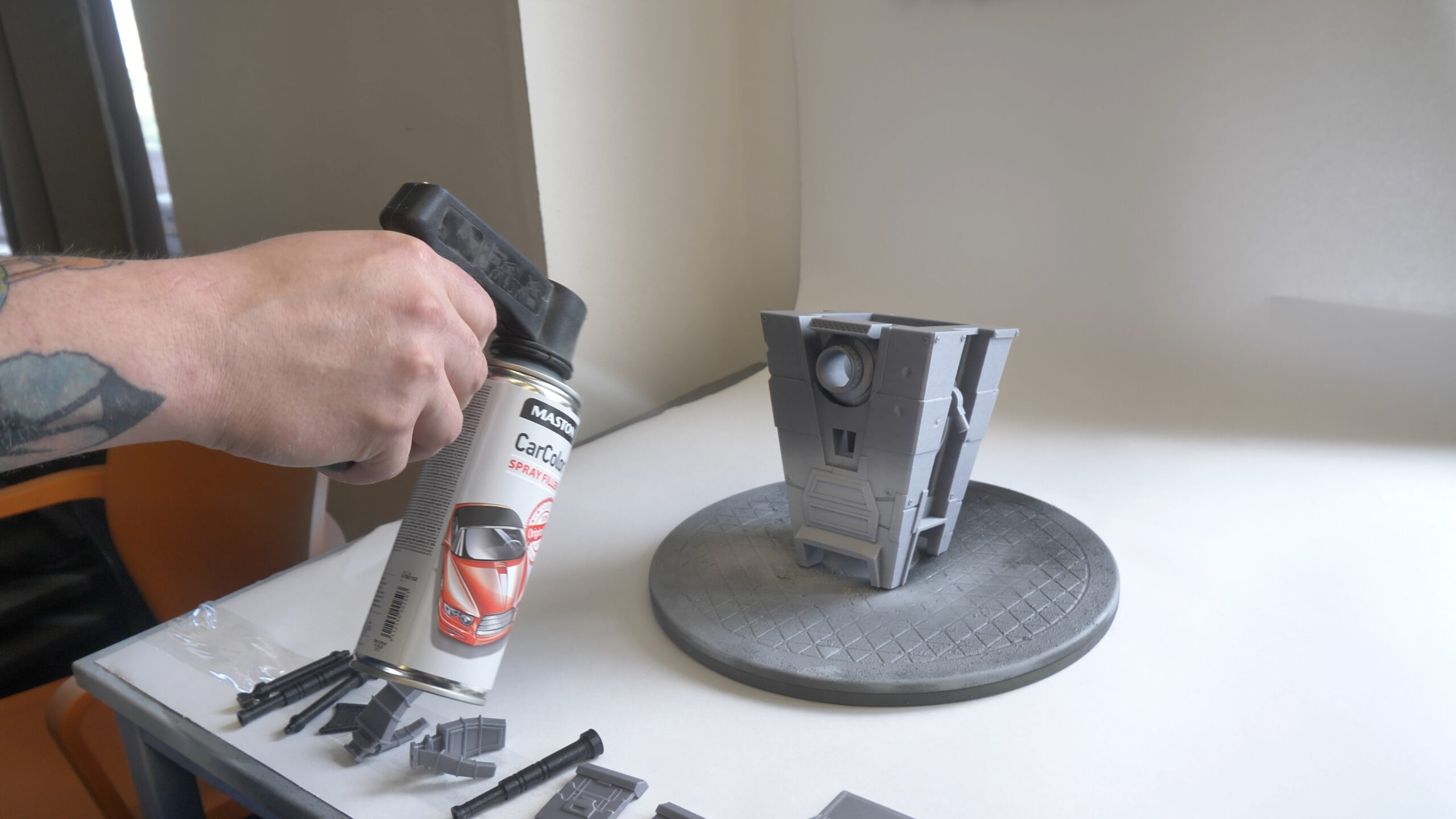
First, we covered the surface with a coat of automotive filler, which will help to hide the layer lines. We covered both the main body and the smaller parts. Big flat surfaces received a quick sanding pass and then we continued with spray painting the parts white. The majority of claptrap is yellow and that’s a very light color that doesn’t cover particularly well. So having a light base color really helps in this case.
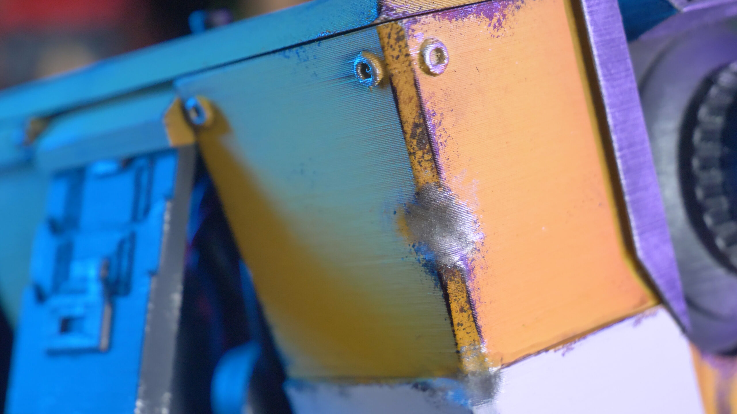
With the white stripe covered with painters tape, we used an airbrush to apply several shades of yellow and orange. Orange color was used on all corners and interesting features to emphasize the shapes and edges. And because Claptrap lives in a wasteland, we also had to start dirtying him up. We brushed brown color into crevices and along the bottom edge of the body. Then, using a sponge, we dabbed darker brown over edges and other prominent features of the model. The dents that we created earlier with sculpting were filled with silver – to imitate exposed metal. And the edges of those dents were highlighted with a brownish color.
The last big color pass was with grey color. We covered all the parts that should remain yellow with painters tape and then sprayed all the exposed surfaces with an airbrush. For the smaller parts, you can use a clamp for easier manipulation. The grey would look way too monotone if we just left it like this. So we used the sponge again to dab the surface with darker grey and silver color. The front vent cover is really small, so we used a brush to paint the inside silver.
A step that’s super effective is dry brushing with silver color to simulate scratches.
We printed two graphics for the front side on a normal A4 office printer, cut them out and glued them in place. We’ve then covered them with a glossy lacquer, once it dries, it will help to make these look like screens.

The base around the wheel was covered with a really interesting Citadel texture paint. It creates a sand-like surface once dry.
The final and most satisfying step is removing the painter’s tape.
Assembly
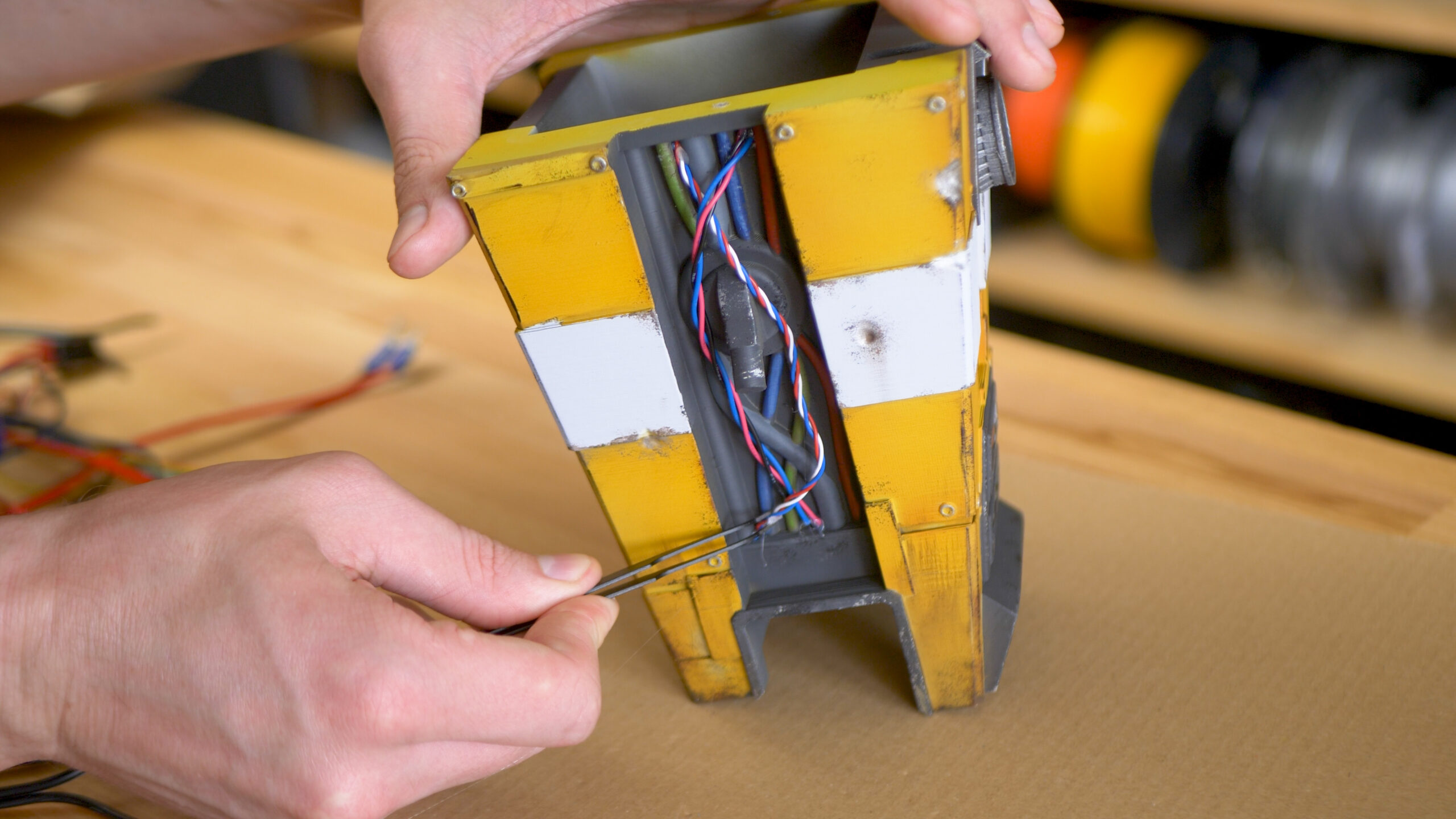
We have a really simple trick that will improve Claptrap’s look even more – hot gluing some real wires to it! The fake printed and painted wires will look much better with some real ones in front of them. Do this first, while you still have easy access to the sides of Claptrap’s body.
The hands have tiny contact areas, so super-glue is better here, but hot glue may be also an option. Then you can glue the wheel with the base to the body. The body sits on the wheel at an angle. If you want Claptrap to look slightly up (when you plan to place him, for example, on a desk), you can rotate the body by 180 degrees. The wheel frame won’t connect to the body perfectly like this, but it’s only visible if you pick Claptrap up and look at him from the bottom, so we decided to go this way anyway.
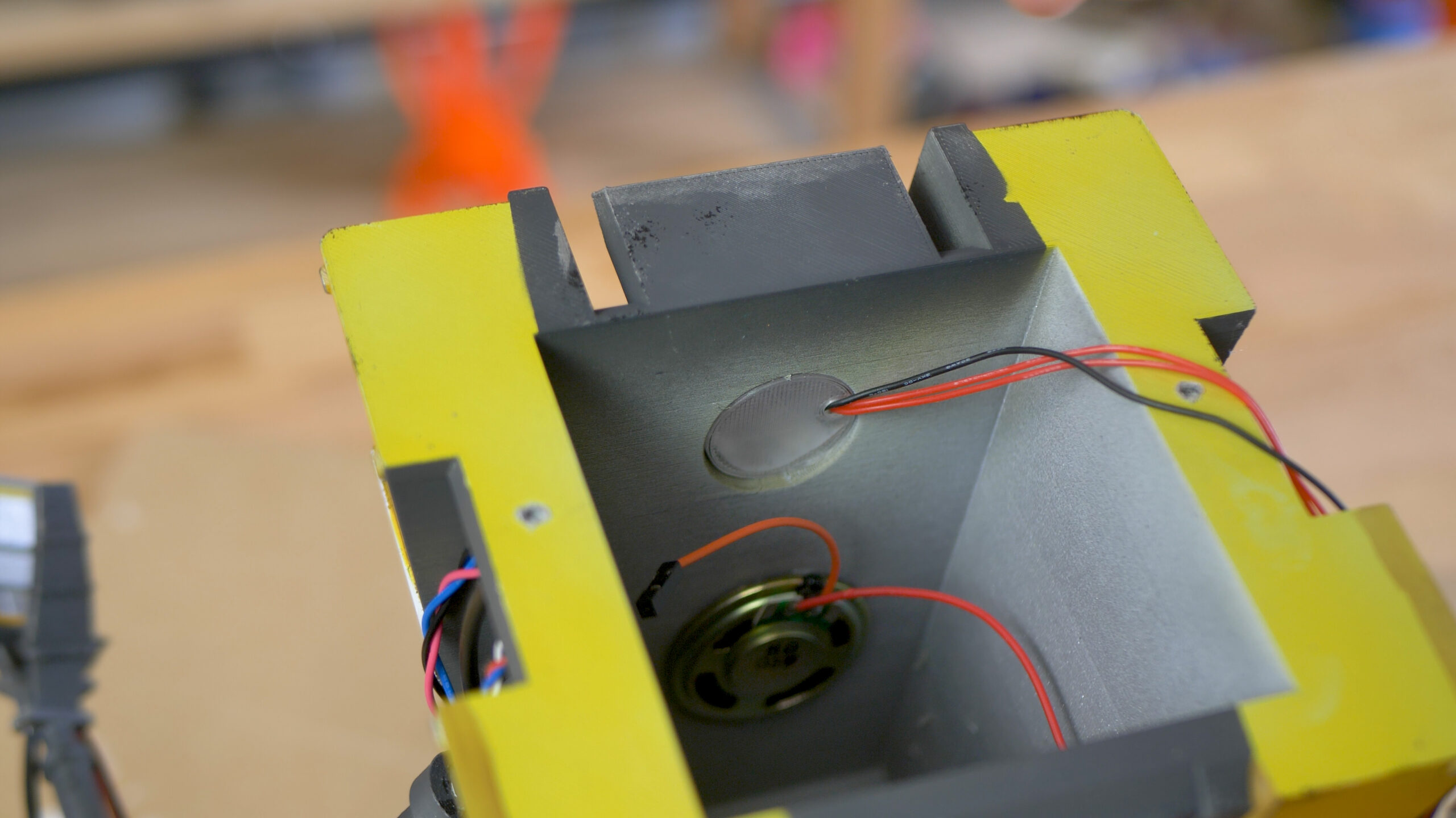
Gluing the speaker to the body has a big impact on the audio loudness. Claptrap’s body will work essentially as a loudspeaker enclosure. The LED holder should just slide in place. And so should the eye lens. Use a tiny bit of glue if they seem loose.
Then glue in the speaker cover. Push the button through the hole in the top cover and connect it to the Arduino board. Now it’s time to connect the power bank and then to carefully screw the top cover to the body. We used two M3x10 screws – if you own an Original Prusa printer, you might have some in the spares bag. The last two pieces to attach are the shoulders, which just slide in place. If you want to keep Claptrap on at all times, you can drill a hole in the back of the body (or modify the STL files) and route a long USB cable through it.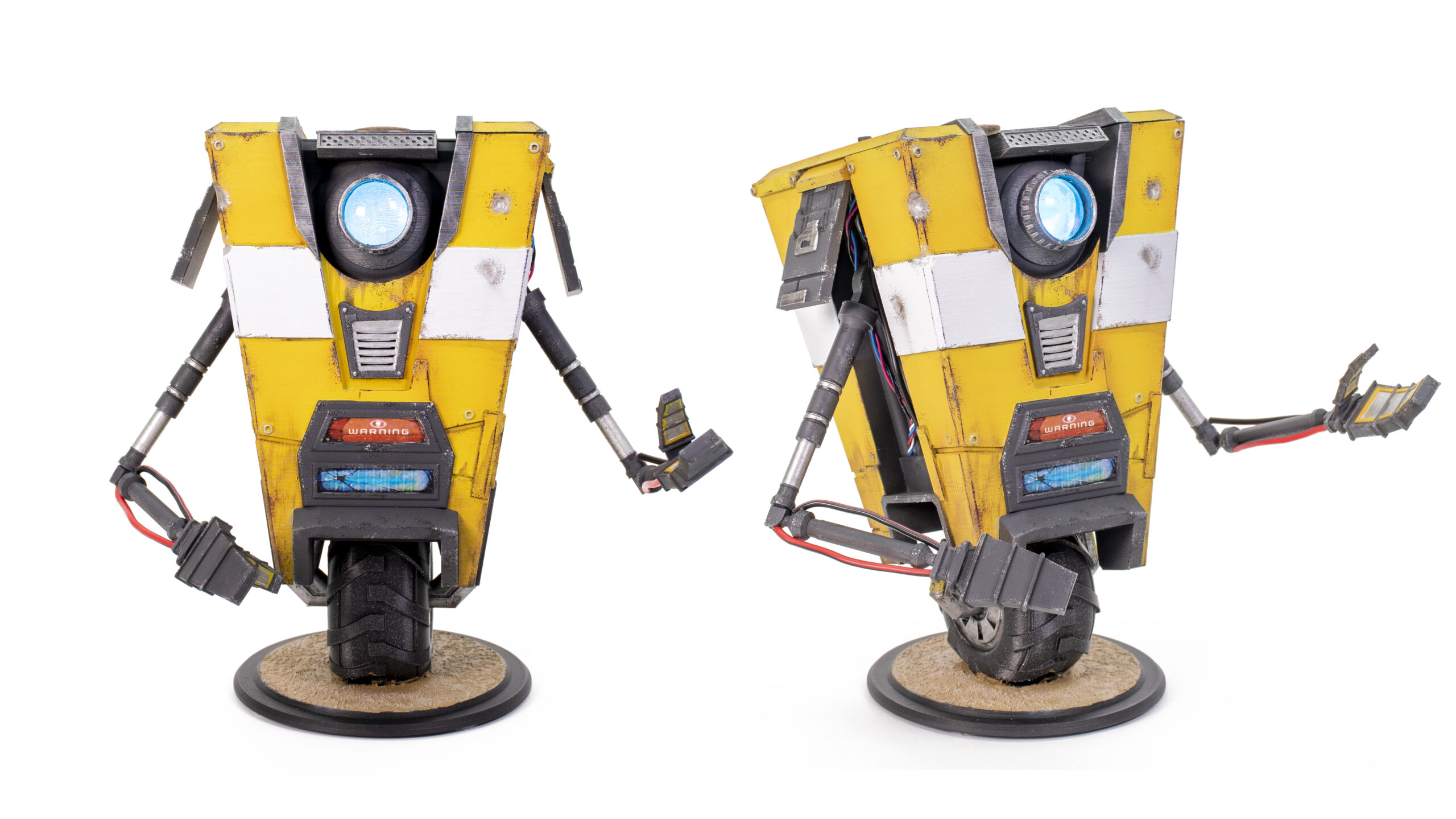
Finished Claptrap
Push the button and enjoy a satirical voice line from our little depressed robot! If you wanted to build a different kind of robot, you would just use a different 3D model and upload different voice lines to the SD card. But otherwise, the process would be more or less identical. And we still have tons of free pins on the Arduino! So the only limit is your imagination. How about some servos to achieve movable parts, an ultrasonic sensor that will trigger voice lines or wireless connectivity to your phone?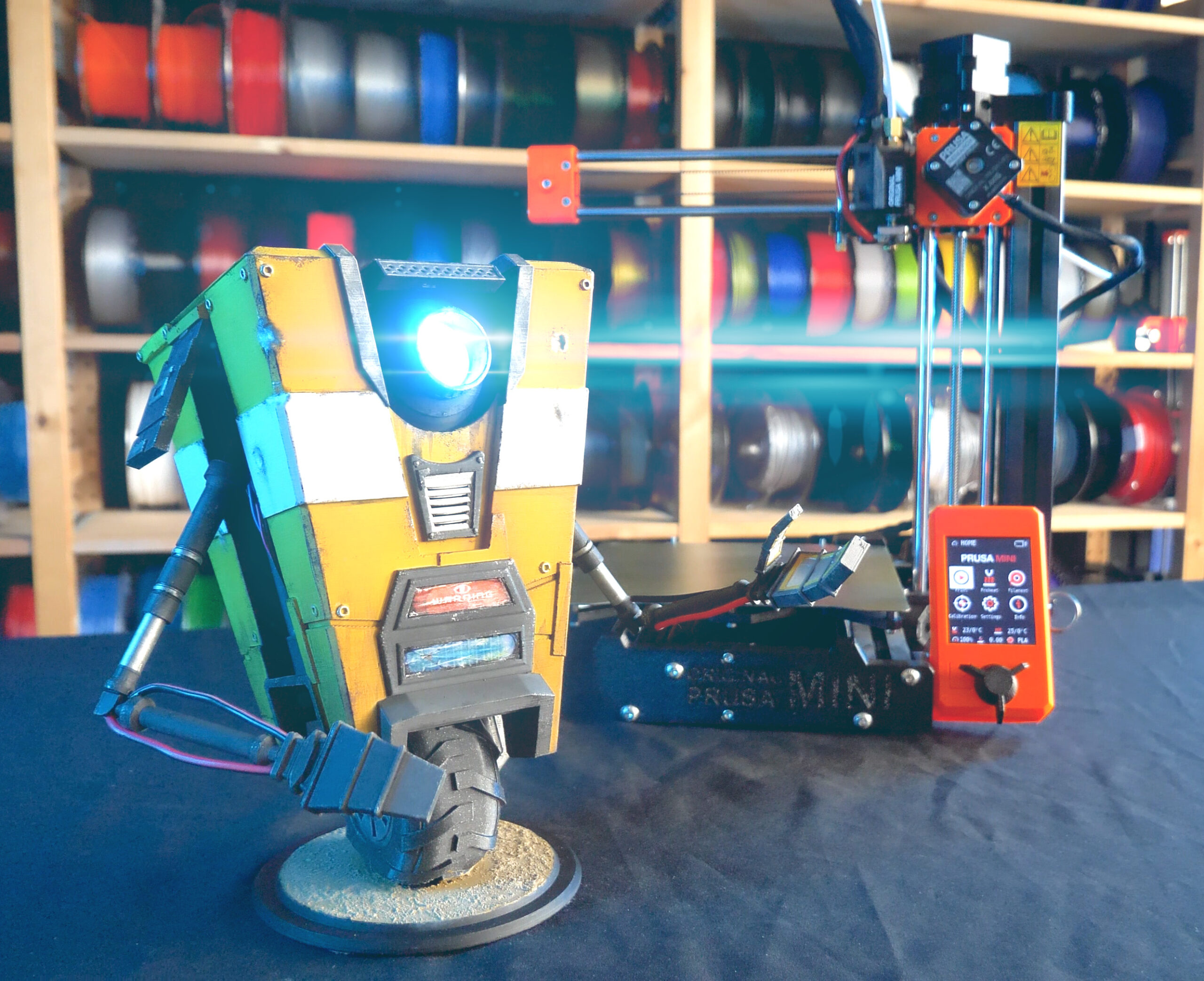
Was this project too complex? Do you have an idea for our next electronics tutorial? Or have you already created something similar? Let us know in the comments!
Happy printing!
More info on power source please. You mention that the Arduino uses 5V but imply, from list of parts, that the power source is a 18650 battery. This battery is rated at 3.7v. How did you configure the power source? Thanks
I think the 18650 is an optional add. The source should be a micro USB (like a phone charger). The wiring diagram shows a Micro USB on the board. Unless I am seeing to much into this.
Thank you, very helpful. 🙂
Hello, what do you mean it is optional? How do I get 5V from 3.7V, or am I supposed to connect this somewhere else?
The battery power is an optional add on, I think the “base” model is to run it off a phone charger.
The Aliexpress link by the 18650 takes you to a page where you are buying the enclosure for an 18650 that has a charging and output circuit. I think the intention is to either use that as a portable power source, or to hack it into place – although it doesnt look like there is much space in the body for the battery, so i think you’d have to scale up the model to get the battery and circuits into place. You’d also want to add some kind of flap to get at the battery to charge it. Also note that these types of cheap battery circuits can’t charge effectively whilst also outputting, so a switch in between the battery and the arduino is a good idea. Or get a battery enclosure that has a switch.
Thank you, I didn’t catch the USB power connection. ;~D
Is there any way we can get the colors (Names/Hex#) used by the model builder please?
You’d also want to add some kind of flap to get at the battery to charge it. Also note that these types of cheap battery circuits can’t charge effectively whilst also outputting, so a switch in between the battery and the arduino is a good idea.
Gmail Klantenservice
I really need a 3D printer. It’s so inspiring to see these photos! I will definitely share some of them https://celltrackingapps.com/how-to-set-up-parental-controls-on-windows/ here.
I followed the instructions for the Arduino Nano, which worked wonderfully once I’d set Arduino to use the old bootloader. I also modified the code to use more sophisticated LED lighting sequences from the example files that come in the LED library, and put it all into a Tardis with appropriate sound files for the son of a friend. Thanks for the inspiration, I didn’t know all this was possible!
Any chance you can point me to the sound bank you used?
I used http://www.orangefreesounds.com/tardis-sound/ but only because it was the first on Google, I’m sure there are lots more.
Does anyone know where you get the photos for the screen bit?
Great question! Also I need help with the Arduino. I am a super noob to this stuff and I cant seem to get it to work. If anyone would be so kind as to help me out, please hit me up [email protected].
Hi again I am a little unsure on how to use and put the resistor in place. Can someone please help me?
Hi Mikolas we are impressed!, we have lot of 3D printable robots in our community (ottodiy.com) but very few with these kind of super cool finish and detail, we could make this one move!, would you guys be interested in a crossover video or project with us?
how long does it take on the mini and what the mass?
I read your blog frequently and I just thought I’d say keep up the amazing work rblx.gg free
Can this be done on a MAC computer? or just a PC?
LOVE The design! We just printed 3 of them for fun!
I have a couple questions about the code, I’m still learning how to read it. haha
First, as soon as I power the Arduino via USB, it just repeatedly clicks the speaker until I hit the reset button. then it works fine. Any idea why?
Second, How do I identify which clip is #1 on the flash drive? I tried naming them as 0001, 0002, 0003, etc.. but it still picks the wrong clip to play when the Arduino boots up. (it’s the same wrong clip even after reboot.)
Third, and the MOST fun one, is it possible to have the LED blink RED for certain clips, then the normal Aqua for the rest? it would be fun to put some of his angry clips on there.
Have a peek on this amazing tracking app https://spydetections.com/
First thank you for this incredible tutorial. Making this for a friend as a gift. I have everything wired up as specified. Everything works, but for some reason when I first power on its like the audio is skipping? Only way I seem to be able to get it to stop is to reupload .ino instructions to the board again and all is well until i unplug it. Anyone else experienced this?
I very rarely leave reviews, but now I can not pass by at all! This is my first betterhelp review, good words about the site that really helped me. I have been struggling with aggression most of my life, at the slightest disagreement I would lose my temper and it was hard to communicate with people. So, here is the best online mental health counseling as the therapists in a word are real professionals. You can see that they find an approach to you and try to fix your problems. There’s also a chat room where you can ask the therapist questions at any time. All in all a very worthwhile service that really solves problems, I recommend everyone!!!
Creating a talking robot with animated drive mad LEDs, inspired by Claptrap from the Borderlands video game series, can be an exciting DIY project.
I spent many hours challenging myself and improving my <a href="https://retro-bowl.io/drift-hunters">Drift Hunters</a> skills in this game